
System
Neuroimaging

Axial Head CT
Head CTs are performed by acquiring discrete, axial slices through the brain, ranging in thickness from 2-5mm/slice. In some cases, the CT data is acquired as a helix of density data which is then reformatted into the axial, coronal, or sagittal planes.
Head CTs can be performed without iv contrast (unenhanced), or following iv contrast injection (enhanced), depending on what the clinical situation is. On enhanced scans, the arteries, veins, dura and meninges all become brighter since they take up the contrast. The blood brain barrier prevents the contrast from being taken up by the brain parenchyma, so it does not become brighter.
This is an enhanced CT of the brain after intravenous contrast was administered.
Identify the following structures:
- Falx Cerebri
- Superior Sagittal Sinus
- Central Sulcus

Axial PD-weighted MRI
MRIs are acquired as thin slices in the axial, coronal, or sagittal planes. PD (proton density) weighting is a technique used to acquire the images that results in a standard, specific appearance of normal tissues. On PD images of the brain, fluid appears light gray, and can be hard to differentiate from gray matter. Gray matter is also light gray, and white matter is darker gray. On PD images, the contrast between white and gray matter is excellent. Most vessels are black. The subcutaneous fat is white.
Identify the following structures:
- Centrum Semiovale
- Superior Sagittal Sinus
- Parietal Lobe
- Falx Cerebri

Axial T2-weighted MRI
MRIs are acquired as thin slices in the axial, coronal, or sagittal plane. T2 weighting describes the technique used to acquire images in a particular way that causes fluid to look bright (white). Gray matter appears mid to light gray, and white matter is darker than gray matter. Most vessels are black. The subcutaneous fat is sometimes white, and sometimes dark, such as if a technique called ‘fat saturation’ has been employed.
Identify the following structures:
- Subarachnoid Space
- Interhemispheric Fissure
- Centrum Semiovale
- Superior Sagittal Sinus

Sagittal T1-weighted MRI
MRIs are obtained as thin slices in the axial, coronal, or sagittal planes. T1 weighting is a technique used to acquire images in which fluid appears dark/black. Gray matter appears dark gray, and white matter is lighter than gray matter. The appearance of blood vessels is variable. In the series that follows, the large vessels, like the carotid arteries and circle of Willis arteries are white. The subcutaneous fat is white.
Identify the following structures:
- Frontal Lobe
- Caudate Nucleus
- Internal Capsule
- Thalamus
- Internal Carotid Artery
- Temporal Lobe
- Cerebellum
- Occipital Lobe
- Choroid Plexus In Lateral Ventricle
- Subarachnoid Space

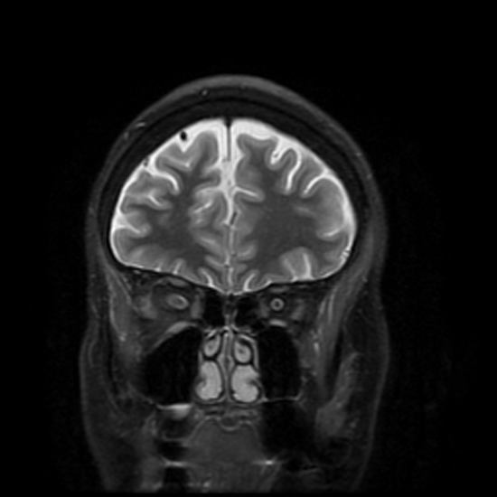
Coronal T2-weighted MRI
MRIs are acquired as thin slices in the axial, coronal, or sagittal plane. T2 weighting describes the technique used to acquire images in a particular way that causes fluid to look bright (white). Gray matter appears mid to light gray, and white matter is darker than gray matter. Most vessels are black. The subcutaneous fat is sometimes white, and sometimes dark, like when a technique called ‘fat saturation’ has been employed, as is the case in the series of coronal images which follows.
Identify the following structures:
- Falx Cerebri
- Subarachnoid Space
- Interhemispheric Fissure
- Anterior Cerebral Artery
- Gray Matter
- White Matter
Conventional Cerebral Angiography
Aortic Arch

These images were aquired by rapid injection of iodinated contrast material through a catheter placed into the ascending aorta, with rapid sequential radiographs obtained.
The image is aquired in a left anterior oblique projection, which optimizes viewing of the arch and great vessels origins. On this image, the bones are included. On the subsequent images, the bones have been 'subtracted', which increases the conspicuity of the opacified vessels.
Identify the following structures:
- Aortic Arch
- Brachiocephalic Trunk
- Right Subclavian Artery
- Right Vertebral Artery
- Right Common Carotid Artery
- Left Common Carotid Artery
- Left Internal Carotid Artery
- Left External Carotid Artery
- Left Subclavian Artery
- Left Vertebral Artery

Internal Carotid (AP)

These images were aquired by rapid injection of iodinated contrast material through a catheter placed into the right internal carotid artery, with rapid sequential radiographs obtained.
The image is aquired in an antero-posterior (AP) projection, which optimizes viewing of the internal carotid artery bifurcation. The cavernous segment of the carotid artery is superimposed, and the bifurcation of the middle cerebral artery is not well visualized in this projection.
On this image, the bones are included. On the subsequent images, the bones have been 'subtracted', which increases the conspicuity of the opacified vessels. Only the proximal aspects of the vessels are opacified well on this early image.
Identify the following structures:
- Right Internal Carotid Artery
- Right Middle Cerebral Artery
- Right Anterior Cerebral Artery
- Left Anterior Cerebral Artery
- Anterior Communicating Artery

Carotid Angiogram Venous Phase
The injected contrast has now passed through the arterial circulation and into the venous circulation, opacifying small cortical veins and the dural venous sinuses.
Identify the following structures:
- Superior Sagittal Sinus
- Transverse Sinus
- Sigmoid Sinus
- Bridging Vein

Internal Carotid (Lateral)

These images were aquired by rapid injection of iodinated contrast material through a catheter placed into the right internal carotid artery, with rapid sequential radiographs obtained.
The image is aquired in a lateral projection, which optimizes viewing of the cavernous segment of the internal carotid artery. The course of the anterior cerebral artery is seen, parallelling the corpus callosum. The bifurcation of the internal carotid artery and middle cerebral artery are not well visualized in this projection.
On this image, the bones are included. On the subsequent images, the bones have been 'subtracted', which increases the conspicuity of the opacified vessels.
Identify the following structures:
- Right Internal Carotid Artery
- Right Middle Cerebral Artery
- Right Anterior Cerebral Artery

Venous Phase
The injected contrast has passed through the arterial circulation and into the venous system, opacifying the cortical and deep veins and dural venous sinuses. The field of view is small, and portions of the patient's skull are excluded from the image; thus the entirety of the superior sagittal sinus is not seen.
Identify the following structures:
- Superior Sagittal Sinus
- Transverse Sinus
- Straight Sinus
- Sigmoid Sinus
- Internal Jugular Vein

Vertebral Artery (AP)
The bones have been subtracted from this image. The contrast has been injected from a catheter placed into the right vertebral artery. Both the right and left vessels originating from the basilar artery will be opacified with either a right or left vertebral injection, and contrast often refluxes down the contralateral vertebral artery.
Identify the following structures:
- Right Vertebral Artery
- Basilar Artery
- Right Posterior Cerebral Artery
- Right Superior Cerebellar Artery
- Right Anterior Inferior Cerebellar Artery
- Right Posterior Inferior Cerebellar Artery
- Left Posterior Cerebral Artery
- Left Superior Cerebellar Artery
- Left Vertebral Artery

Venous Phase
Contrast has passed through the arterial circulation and into the veins, opacifying the dural venous sinuses draining the occipital lobes and cerebellum.
Identify the following structures:
- Superior Sagittal Sinus
- Transverse Sinus
- Sigmoid Sinus
- Internal Jugular Vein

Vertebral Artery (Lateral)
Identify the following structures:
- Right Vertebral Artery
- Basilar Artery
- Posterior Cerebral Artery
- Superior Cerebellar Artery
- Anterior Inferior Cerebellar Artery
- Posterior Inferior Cerebellar Artery

Venous Phase
Contrast has passed through the arterial circulation and into the veins, opacifying the dural venous sinuses draining the occipital lobe and cerebellum. The right and left transverse and sigmoid sinues and internal jugular veins are opacified and overlap on the image.
Identify the following structures:
- Superior Sagittal Sinus
- Confluence Of The Sinuses
- Transverse Sinus
- Sigmoid Sinus
- Internal Jugular Vein

Non-Invasive Cerebral Angiography
CT Angiography

These images were aquired with CT following rapid injection of iodinated contrast material through an arm vein. The scan was obtained while the contrast was located in the arterial circulation.
The data has been reformatted into a 3D image with a volume rendering technique. Only high density structures, like the contrast opacified vessels and the skull base, are displayed in this image. View the image as though the calvarium has been removed and you are looking down onto the skull base and circle of Willis.
CT Angiogram Anterior Circulation
This is a 3D volume rendered image of the anterior circulation, seen from an AP projection.
Identify the following structures:
- Left Internal Carotid Artery
- Left Middle Cerebral Artery
- Left Anterior Cerebral Artery
- Anterior Communicating Artery
- Right Anterior Cerebral Artery

CT Angiogram Posterior Circulation
This is a 3D volume rendered image of the posterior circulation, seen from an AP projection.
Identify the following structures:
- Basilar Artery
- Left Posterior Inferior Cerebellar Artery
- Left Superior Cerebellar Artery
- Left Posterior Cerebral Artery
- Left Vertebral Artery

MR Angiography
MR Angiography - Brain (AP)
MRA of the circle of Willis vessels can be performed without iv contrast enhancement. The technique capitalized on the properties of flowing blood. Vessels appear white on this type of image, and the background tissues are suppressed.
The images are reformatted to demonstrate the anterior and posterior circulation separately.
Identify the following structures:
- Left Internal Carotid Artery
- Left Middle Cerebral Artery
- Left Anterior Cerebral Artery
- Right Anterior Cerebral Artery
- Right Middle Cerebral Artery
MR Angiography - LAO projection
This image is obtained in the left anterior oblique (LAO) projection, which shows the cavernous segments of the internal carotid artery and the middle cerebral artery bifurcation better than the AP projection.
Identify the following structures:
- Left Internal Carotid Artery
- Left Middle Cerebral Artery
- Right Internal Carotid Artery
- Right Anterior Cerebral Artery
- Right Middle Cerebral Artery

MR Angiography - RAO projection
This image is obtained in the right anterior oblique (RAO) projection. By viewing both the LAO and RAO projections, the bifurcations of the middle cerebral and internal carotid arteries can be accurately evaluated on both the right and left sides.
Identify the following structures:
- Left Internal Carotid Artery
- Left Middle Cerebral Artery
- Left Anterior Cerebral Artery
- Right Internal Carotid Artery
- Right Anterior Cerebral Artery
- Right Middle Cerebral Artery

MR Angiography - Posterior Circulation (AP)
This image shows only the posterior circulation. The anterior circulation has been removed from the data displayed.
Identify the following structures:
- Right Vertebral Artery
- Left Vertebral Artery
- Basilar Artery
- Right Anterior Inferior Cerebellar Artery (Aica)
- Left Anterior Inferior Cerebellar Artery (Aica)
- Right Superior Cerebellar Artery
- Left Superior Cerebellar Artery
- Right Posterior Cerebral Artery
- Left Posterior Cerebral Artery

MR Angiography - Posterior Circulation (Lateral)
This image shows only the posterior circulation. Since the vertebral arteries and branches of the basilar artery are superimposed, the right and left cannot be distinguished.
Identify the following structures:
- Right And Left Vertebral Arteries
- Basilar Artery
- Right And Left Posterior Cerebral Arteries

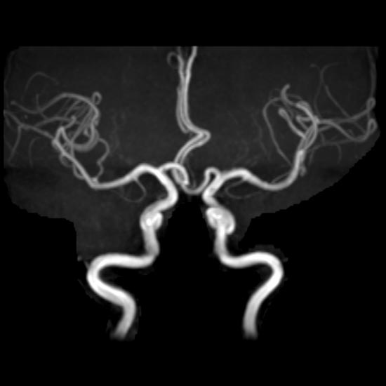
Circle of Willis: MR and CT Angiograms
Both of the images shown are reformatted images from an CT angiogram and MR angiogram of the head. Both are viewed from a superior aspect; as though the brain has been removed and you are looking at the circle of willis from above. The anterior cranial fossa is at the top of the image, and the foramen magnum would be at the bottom of the image. Notice the anatomy seen with each is slightly different; on the MRA, the entire course of the internal carotid arteries is visible, while on the CTA, it is partially obscured by the dense bone. Images are from two different patients.
Identify the following structures:
- Basilar Artery
- Posterior Cerebral Arteries
- Superior Cerebellar Arteries
- Internal Carotid Arteries (Cavernous Segments)
- Middle Cerebral Arteries
- Anterior Cerebral Arteries
- Anterior Communicating Artery
- Vertebral Arteries

MR Venography
MR Venography (AP)
These images are created without using IV contrast. The technique used capitalizes on the magnetic properties of flowing blood, which appears white on the image. The background tissues are suppressed.
Identify the following structures:
- Superior Sagittal Sinus
- Transverse Sinus
- Sigmoid Sinus
- Internal Jugular Vein
- Confluens Of Sinuses

MR Venography (Lateral)
Structures on the right and left sides of the head are superimposed on this image. Intravenous contrast is not needed for this technique.
Identify the following structures:
- Superior Sagittal Sinus
- Transverse Sinus
- Sigmoid Sinus
- Straight Sinus
- Internal Jugular Vein
